Wednesday, 15 January 2014

Electronics Books Free Download

Be The First To Comment
Electronics Books Free Download


 Here you can easily Download any Electronics Book
  1. 8051 Programming Tutorial Book (1)
  2. 8051 Programming Tutorial Book (2)
  3. Antenna Design
  4. Brushless DC (BLDC) Motor Fundamentals
  5. business_model_canvas_poster
  6. business_model_canvas_poster
  7. C++_By_Dissection_(2002)
  8. Data_Communications_and_Networking_-_Behrouz_A._Forouzan
  9. ebooksclub.org__Confronting_Climate_Change__Shortcuts_
  10. Filters
  11. Java How to Program 9th Edition
  12. Linux C++ Programming HOWTO
  13. Robot Simulator
  14. Sams Teach Yourself C++ for Linux in 21 Days
  15. Startup An Insider’s Guide to Launching and Running a Business

Tuesday, 24 December 2013

Color Detection Using LDR | Sensor Using LDR | Sensors theory of working | Light Sensors | Street Light Project

Be The First To Comment

Color Detection Using LDR | Sensor Using LDR | Sensors theory of working | Light Sensors | Street Light Project 

LDR SENSOR FOR COLOR DETECTION

summary:-

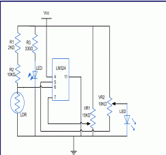
This circuit can be used to sense and differentiate between different colors. This project demonstrates the principle and operation of a simple color sensor using LDR. The circuit is divided into three parts: Detector (LDR), Comparator and Output. This circuit is based on LM324 IC whose pin diagram has been shown below:

Circuit diagram:-

ldr colour detection
Component:-
  1. Resistor
  2. LED
  3. LDR
  4. Preset
  5. IC LM324
Description of making LDR Sensor :-
In this project, when light of a particular color falls on LDR, its resistance decreases and an output voltage is produced. This voltage is dependent on the intensity and wavelength of different color. For this we need to set reference voltage of comparator according to our requirement.
For Eg., If we set reference voltage at positive pin with 0.38volts, the LDR becomes sensitive to blue light. When blue light falls on the LED, an output of approximate voltage 0.28V is produced, this glows the output LED.But if we use a yellow color light on LDR then input voltage at the comparator is around 0.7 volts at the negative pin of comparator and the output LED doesn’t glow.


Monday, 23 December 2013

How To Use Adc With 8051 Microcontroller In Proteus

Be The First To Comment

   How To Use Adc With 8051 Microcontroller In Proteus 

How to interface adc0808 with 8051 microcontroller

The following circuit  diagram  shows the required 8051 microcontroller circuit.

how to use adc with 8051 microcontroller
In this  circuit, 8 bit data bus of ADC0808 is attached with 8051 on Port 0. control signals of ADC0808 are connected  on Port 2 of 8051 micro controller. LCD is connected on Port  1, LCD is used to show the output  of ADC.

ADC0808 has 8 input channels so at a time 8 sensors can be connected. You can use any channel for ADC purposes in the code. A potentiometer (i-e variable 10k resistor) is connected on IN1 of ADC0808 just to demonstrate how to use this code. Input voltage at IN1 is read in the code and displayed on the LCD.  ADC0808 gives an output of 8bit value, so a voltage value of 0v at IN1 will mean ADC value of 0 and a voltage of 5v at IN1 pin means ADC value of 255. In the above figure, it is clear that a voltage of 2.5v is applied on IN1 pin and ADC value of 127 (i-e half of 255) is displayed on the LCD correctly.

A crystal of 12MHz value is used in this circuit, which makes this 8051 (i-e AT89C51) run at a speed of 1MIPS .

Code

The code is shown below.
8051 codes for adc0808

In the main function, firstly pins attached with ADC0808 are initialized using InitADC(); statement, then LCD is initialized using InitLCD() function. Then "Starting..." is displayed on the LCD for one second. After that LCD screen is cleared.

In the while(1) loop, ADC_Value = ReadADC(AN1); statement reads value from IN1 pin of ADC0808 and assigns this value to ADC_Value variable. Next 3 statements are converting ADC_Value in to digits, which will be displayed on the LCD screen. After that, LCD screen is cleared and ADC value is displayed on the LCD.

InitADC() function is shown below.

adc 0404

In the InitADC() function shown above, pins attached to ADC0808 are initialized properly. Also, data bus attached with Port 0 is initialized as well.

ReadADC() function code is shown below.
adc0808

ReadADC() function (shown above) returns 8 bit ADC value. This value is read from a channel, which is the input argument to ReadADC() function. Channel can have a value of AN0 for IN0 pin of ADC0808 or AN1 for IN1 pin etc. For example, to read voltage value at IN7 pin of ADC0808, you can use the statement ReadADC(AN7);.
This is all about 8051 with adc0808


HOW TO USE A TRANSISTOR AS AN AMPLIFIER

Be The First To Comment

HOW TO USE A TRANSISTOR AS AN AMPLIFIER

transistor characteristics and parameters


HOW TRANSISTOR WORKS AS AN AMPLIFIER

As we know transistor is a current control device, it is used for controlling the current in electronics circuits.Transistor is an electronic device used in a circuit to control a large amount of current or voltage with a small amount of voltage or current.
Two layers sandwiching one semiconductor between two other semiconductors. Because the current is transferred across a material that normally has high resistance (i.e. a resistor), it was a "transfer-resistor" or transistor.
The first practical  transistor was made  in 1948  by Shockley,

How a transistor works

for understanding how a transistor works, you have to understand how semiconductors react to an electric potential. Some semiconductors will be n-type, or negative, which means that free electrons in the material drift from a negative electrode (of, say, a battery it's connected to) toward the positive.

                                                                                     Now, we are taking the example of  a npn transistor. Each end of the transistor is an n-type semiconductor material and between them is an p-type semiconductor material. If you picture such a device plugged into a battery, you'll see how the transistor works:
  • We are taking npn transistor because of in this the mobility of charge carriers is high as compare to PNP transistor.
  • the n-type region attached to the negative end of the battery helps propel electrons into the middle p-type region.
  • the n-type region attached to the positive end of the battery helps slow electrons coming out of the p-type region.
  • the p-type region in the center does both.

PNP BJT Common Emitter Characteristic

HOW TRANSISTOR WORKS AS AN AMPLIFIER

Bipolar Junction Transistors


Bipolar Junction Transistors

Bipolar Junction Transistors


Common Emitter Amplier

Common Emitter Amplier

DC analysis: An emitter resistor is necessary to provide stability of the bias point.  We need to include RE for good biasing (DCsignals) and eliminate it for AC signals.The solution to include an emitter resistance and use a "bypass" capacitor to short it out for AC signals as is shown.

Common Emitter Amplier

AC analysis of bjt

To start the analysis, we kill all DC sources, combine R1 and R2 into RB and replace the BJT with its small signal model. We see that emitter is now common between input and output AC signals (thus, common emitter ampli er. Analysis of this circuit is straightforward. Examination of the circuit shows that:

AC analysis of bjt

AC analysis of bjt

BJT current and voltage Equations :-


BJT current and voltage Equations
npn                                                                      pnp

IE = IB + IC                                                IE = IB + IC

VCE = -VBC + VBE                                         VEC = VEB - VCB


Modes of Operation of bjt

Active region of bjt:      

·         Most important mode of operation
                  ·         Central to amplifier operation
                    ·         The region where current curves are practically flat

         Saturation region of bjt:


  •   Barrier potential of the junctions cancel each other out causing a virtualshort

         Cutoff region of bjt :

Current reduced to zero
Ideal transistor behaves like an open switch


Electronics Projects Circuits   Created  By Muhammad Irfan

About Electronics Projects Circuits

Be The First To Comment

                              About Electronics Projects Circuits

 Asalam-O-Alaikum , The Electronics Projects circuits is a Blog that gives you information  about Electronics Projects circuits (Hobby Electronics Projects) .Also my blog consists on some categories such as ,digital electronics ,Arduino based projects ,Microcontroller  based Electronics projects ,robotics Electronics Projects ,Timer circuits,Alarm and security based electronics projects ,some audio circuits and much more coming soon . 
                                       Also my all post give u some important and useful Electronics Circuits such as water level indicator ,  mobile jammer  circuit and much more stay connected with Electronics Project Circuits .                 


                     Buy Buy                                                             Electronics Projects Circuits
 

© 2011 Electronics Projects Circuits - Designed by Mukund | ToS | Privacy Policy | Sitemap

About Us | Contact Us | Write For Us